
There’s a box with a button on the table. You press it, and suddenly there’s loud music, colorful lights flashing, and obviously a wild party going on everywhere. Well… almost. In this case, there’s one light blinking merrily and a song being played. But still, kinda fun.
The idea for the party box came because our kid is learning how to brush his own teeth, and he needs a timer for 2 minutes he’s supposed to brush them. Initially, we had an egg timer to count the time, but it turns out you occasionally need that timer elsewhere, and it’s a bit of a hassle to move it back and forth between the bathroom and the kitchen. More importantly, this was obviously a top priority parenting issue that required a high-tech engineering solution, preferably with DIY electronics and lots of soldering.
Plan
The Party Box is a simple music box with a button that, once pressed, plays a random 2-minute music sample while flashing a bright led inside the button. There’s also an on/off switch to power off the device to save the batteries. For a video of the final product, see bottom of the post.
Parts:
- Arduino Nano clone for logic
- DFPlayer, a 3 € mp3 module with inbuilt amplifier and micro SD-card reader
- 4 GB micro SD card (a much smaller would have been enough, but I couldn’t find one)
- A small speaker (1.5 € “Micro Speaker 20mm X 30mm 8 Ohm 8r 1w” from ebay)
- 4x 1.2V rechargable batteries in a battery pack
- On/off switch
- Party button – a salvaged heavy-duty press button switch
- Bright green led – salvaged from a broken mini flashlight, to be put inside the button
- 2x 1 kΩ and 1x 100 Ω resistors
- Mini-USB connector for powering the Arduino
- Bunch of wires for connections and insulation tape
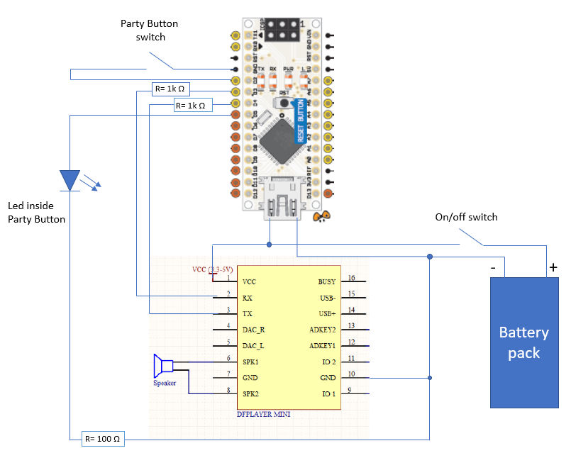
(Image uses the excellent Arduino Nano pinout from http://www.pighixxx.com/test/pinouts/boards/nano.pdf under CC BY-SA. The DFPlayer pinout is from the DFPlayer datasheet.)
Since the circuit uses 4 x 1.2 = 4.8 V batteries as the voltage source to power the Arduino through the USB connector, the output voltage for the GPIO pins is also 4.8 V, at best. In practice, this can drop to 4 V or even lower, with the batteries getting discharged. This doesn’t seem to be a problem for the Arduino, and the DFPlayer can take in voltages in range 3.3…5 V, also.
I didn’t have the specs for the LED, but after some testing, I measured the voltage drop as about 2.3 V. Typical LEDs have a 20 mA current limit, so calculating the voltage drop for the required current limiting resistor gives:
4.8 V – 2.3 V= 2.5 V
U = R I → R = U / I = 2.5 V / 20 mA = 125 Ω
However, I ended up choosing a 100 Ω resistor for the job, because the batteries typically have a lower voltage after being emptied for a while, and LEDs can (typically) easily take 30 mA currents. Using a slightly larger resistor gives only a slightly dimmer light, so the exact value is not that big an issue here.
Note that the DFPlayer is not powered through the Arduino, but is in parallel. Initially, I though it as a good idea to power the DFPlayer through the 5V pin, but this made me fry my first Arduino. Turns out that since the DFPlayer has a 3W amplifier, it can potentially use quite a lot of current:
P = U I → I = P/U = 3 W / 5 V = 600 mA
And because the Arduino Nano regulator can handle only up to 200 mA current, this can break it. Well, luckily I had spare Arduinos, and I consider this simply a valuable lesson learned.
Program Logic for Arduino
I used the DFRobotDFPlayerMini Library to control the DFPlayer, and LowPower.h to enter a low-power energy-save sleep state, when the button has not been pressed for a while and a song is not being played.
#include "Arduino.h"
#include "SoftwareSerial.h"
#include "DFRobotDFPlayerMini.h"
#include <LowPower.h>

#define wakePin 2  // for Party Button
#define ledPinPWM 5

int state_counter= 0;
int sleepState=0;

SoftwareSerial mySoftwareSerial(4, 3); // control DFPlayer
DFRobotDFPlayerMini myDFPlayer;

//-------------------------------------------------
void wakeUp() // here the interrupt is handled after wakeup
{}
//------------------------------------------------------------

void setup() {
 Serial.begin(57600);
 randomSeed(analogRead(0)); // get true random seed for the pseudo-rng
 mySoftwareSerial.begin(9600);
 if (!myDFPlayer.begin(mySoftwareSerial))
   Serial.println(F("PLAYER Unable to begin"));

 pinMode(wakePin, INPUT_PULLUP);
 pinMode(ledPinPWM, OUTPUT);

}

//------------------------------------------------------------

void loop() {

//On first loop we enter the sleep mode
 if(sleepState == 0){
  Serial.println("Going to sleep. Sleepstate -->0");
  attachInterrupt(0, wakeUp, LOW); // interrupt 0 (pin 2) when pin 2 gets LOW
  analogWrite(ledPinPWM,0);

  state_counter=0;
  LowPower.powerDown(SLEEP_FOREVER, ADC_OFF, BOD_OFF); //enter sleep mode
  detachInterrupt(0); //execution resumes from here after wake-up
  Serial.println("Woke Up! Sleepstate 0-->1");
  sleepState=1;
  int song=random(1,7); // I have 6 songs on the SD card
  myDFPlayer.volume(27); // max volume=30
  myDFPlayer.play(song);
 }
 else if(sleepState==1){
  int blink_time=100*60*2; // 2mins; 1 state_counter tick equals 10ms
  if(state_counter>blink_time)
   sleepState=0; // go back to sleep
 }

 // Produce a (limited) triangle wave to blink the LED using PWM
 int period=400; // = 4000ms
 int led_mod=state_counter % period;
 if(led_mod>(period/2)) led_mod=period-led_mod;
 int upper_limit=(period/2)*0.95;
 int lower_limit=(period/2)*0.05;
 led_mod=max(lower_limit,led_mod);
 led_mod=min(upper_limit,led_mod);
 int led_power=map(led_mod, lower_limit, upper_limit, 0, 255);
 analogWrite(ledPinPWM,led_power);

 delay(10);
 state_counter+=1;

}
The blink effect for the LED is achieved using pulse-width modulation. The code calculates the duty cycle as a function of state_counter (which is simply an increasing counter), producing a triangle wave capped at 5% and 95% of min/max values. The triangle wave is then used to set the LED’s brightness. The min/max limits, period, and delay between change in state_counter were chosen purely by what looked most pleasing to the eye.
Update: Improved randomization for the playlist.
Music
I recorded 6 2-minute samples of my kid’s favorite songs (themes from pokemon, super mario, paw patrol, etc.) from youtube using Audacity. See here for more info how.
After recording, I cut/pasted each song sample to be about 120 seconds (dentists’ recommendation) with appropriate fade-outs where necessary, and amplified the sample as much as possible without clipping, since it was going to be played from inside a closed box. I’ve used Audacity also before for small music sample editing, and have found it the best available free software for such purposes.
After exporting to mp3 format, the samples were put into the micro SD card into folder mp3/ with names 0001.mp3 … 0006.mp3. The file and folder naming is required by the DFPlayer.
Putting It Together
I used a cardboard box from my 8bitdo controller as the case for the project. However, the heavy-duty push button was slightly higher than the insides of the box, so I needed additional cardboard pieces to lift the top about 1 centimeter.

On/off switch at the bottom:

The Arduino uses about 3 mA during sleep mode, which is not much, but the DFPlayer also has a 20 mA standby current. This drains the battery pack in a couple of days, so to prolong the battery life, it’s useful to be able to shut down the circuit completely when not in use. Currently, it seems I have to recharge the batteries perhaps once a week – quite often I forget to switch off the device.

Initially, I used a re-purposed headphone as the speaker (see above). This gave more like a beeper- than a speaker-quality sound, so I switched to an actual mini speaker once it arrived in the mail. Still, for a beeper-type sounds, this can be an OK solution for some projects.
Final Product
The Party Button has now been in use for a couple of weeks. My kid likes it, and looks forward to get to press it when it’s time to brush the teeth, which makes the process a bit easier. The egg timer is back in kitchen where it belongs. So far, great success!

